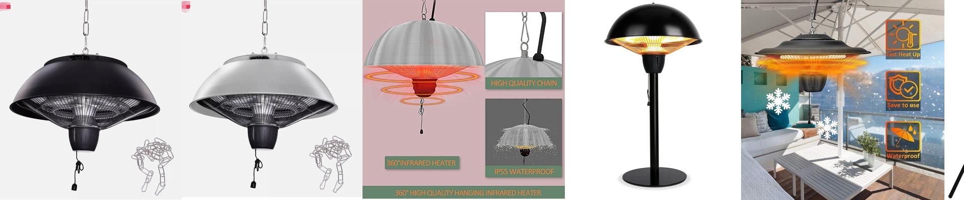
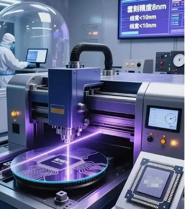
Out on the floor, the flip chip bonder is humming. Pick-and-place cycles, underfill dispenses, and the thermal profile is supposed to stay inside a tight window. When the lamp starts slipping, you know it instantly: cold spots across the substrate, bondline voids, intermetallic variability—and the scrap pile starts to climb. Every minute of temperature drift costs yield. Every unplanned stop costs schedule. We built this flip chip bonding heater lamp for exactly that reality—where the thermal budget is fixed and repeatability is the only outcome that matters.
What actually matters, technically
This lamp is all about controlled radiation and stable thermal delivery. Depending on the process, we spec the emitter as short-wave halogen, medium-wave quartz, or near-infrared (NIR) carbon fiber—chosen to match absorption in the substrate, solder, and adhesive stack. The point isn’t hitting some peak temperature. It’s hitting the same temperature at the bond interface, cycle after cycle. The specs are chosen to fit real production constraints:
- Thermal uniformity: ±0.1 °C across the active zone, measured on a calibrated test coupon under production airflow.
- Photoresist bake compatibility: Soft bake and hard bake profiles repeatable within ±0.5 °C setpoint stability—so lithography-linked thermal steps don’t introduce overexposure or residual stress.
- Cleanroom compatibility: Materials and seals rated for Class 1–100 environments, with construction that keeps outgassing and particle shedding low.
- Particle performance: Zero particle generation during steady-state operation, verified by in-situ particle monitoring at the tool level.
- Reliability: Built for 24/7 operation with zero unplanned downtime targets, backed by life data and controlled maintenance intervals.
- Power and interface: Standard voltages (100–240 VAC) in a compact footprint, with connector options that line up to common bonder and oven modules. The control approach is intentionally straightforward: ramp fast, regulate tightly, settle quickly. The controller holds setpoint despite line fluctuations and shifting thermal loads, and the optics and reflector geometry keep the energy where it belongs—on the bond site, not on the frame.
Why this works where the work happens
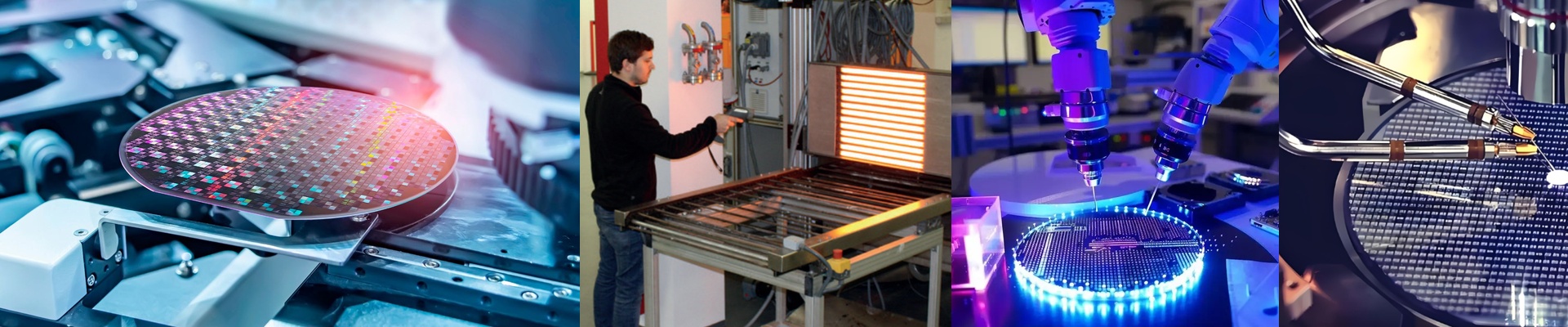
Flip chip bonding is precision assembly driven by heat. You control position, force, and time, but the metallurgy and adhesion are set by temperature. If the lamp varies across the array, you get non-uniform reflow and inconsistent underfill cure. If it lags, cycle time stretches and the thermal budget drifts. This lamp attacks those failure modes head-on. Wafer-level and panel-level flip chip Whether you’re running wafers or large panels, the lamp delivers uniform heat with tight edge-to-edge control. That cuts scrap from warpage-induced misalignment and reduces rework from marginal bonds. Process windows widen because the thermal profile stays in spec, lot after lot. Photoresist processing alignment When thermal steps bridge lithography and assembly, the lamp has to behave like a litho tool, not a hot plate. It holds stable setpoints for soft bake and hard bake, giving you consistent photoresist behavior—consistent thickness, consistent line integrity, predictable residue behavior. Fewer defects carry forward into packaging. Cleanroom operation and contamination control In Class 1–100 cleanrooms, particle count is part of the process spec. The lamp’s construction prevents shedding and limits outgassing, so you aren’t chasing excursions caused by the heating source. It’s also built to clean: surfaces and seals are specced for standard cleaning agents and wipe protocols. Uptime and repeatability Production schedules don’t forgive random stops. The lamp runs continuously, with predictable maintenance and stable output over thousands of hours. When the lamp isn’t the variable, you spend less time tuning and more time shipping.
The details that make the difference
No component lives in a vacuum. The lamp performs best when the system around it is set up for it.
- **Airflow matters.**Uniformity depends on controlled airflow around the lamp and substrate. If airflow is uneven, you’ll see local gradients even with a stable lamp. Map the airflow first, then set the lamp.
- **Emitter selection is process-dependent.**Short-wave, medium-wave, and NIR aren’t interchangeable. Match the spectrum to the absorption profile of the materials at the bond interface. If you run multiple material stacks, plan for configurable emitters or a modular lamp head.
- **Integration details.**The lamp needs to align mechanically and thermally with the bonder or oven module. Confirm mounting, clearance, and connector compatibility during installation. Expect a short commissioning period to lock in the thermal profile and validate particle performance.
- **Power infrastructure.**Stable voltage and grounding reduce noise and drift. If your line has high transients, add line conditioning. The lamp is tolerant, but precision starts at the power input. If you’re running flip chip at scale, the heater lamp isn’t an accessory—it’s part of the process control loop. Spec it like it matters, install it with intention, and it will keep the thermal profile honest, shift after shift.